Final Project Ideas and Iteration
Wellcome to the Journey of trying to fabricate a sensory Hiden Shelf
Wellcome to the Journey of trying to fabricate a sensory Hiden Shelf
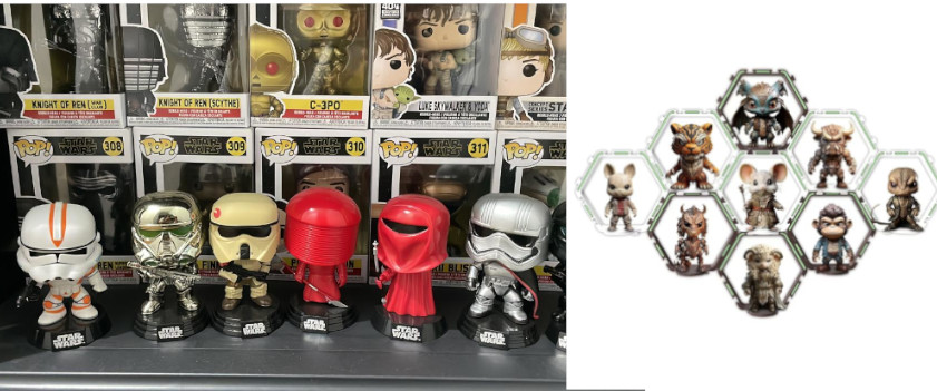
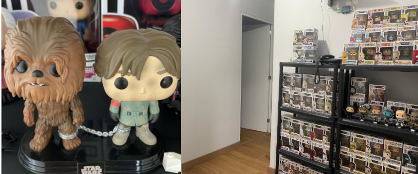
 I'm Funko Pop collector, kind of bubble head toys. I
started having just a few of them from Star Wars franchise, but my collection increase to almost 200
units. So, I started to having problems related to store them, but also about how can be showcased.
Within this kind of collectable items there are some of them that are really valuable and unique, that
need to be protected.The problem is now only about storage, my major problem is related with people
intending to open the collectable boxes and trying to play or joke with some valuable items, without
following any protocol endangering risk their value. I intended to showcase some open funkos
to aovid this kind of problems. Distributing them between different shelves
around my house.
I'm Funko Pop collector, kind of bubble head toys. I
started having just a few of them from Star Wars franchise, but my collection increase to almost 200
units. So, I started to having problems related to store them, but also about how can be showcased.
Within this kind of collectable items there are some of them that are really valuable and unique, that
need to be protected.The problem is now only about storage, my major problem is related with people
intending to open the collectable boxes and trying to play or joke with some valuable items, without
following any protocol endangering risk their value. I intended to showcase some open funkos
to aovid this kind of problems. Distributing them between different shelves
around my house.
 So I have been
exploring different
options from
commercial shelves (not customize for funkos), just regular vertical shelves to store them
without showcase special items, to highly customize thematic shelves. Thus, I look for inspiration by shearching
diferent geometric designs that could cover completly a wall. I found some commercially
and cumtomized options available in other countries. So I decide to drawn some ideas that could be
applied and thinking about how I can be produced it locally using digital fabrication technologies.
So I have been
exploring different
options from
commercial shelves (not customize for funkos), just regular vertical shelves to store them
without showcase special items, to highly customize thematic shelves. Thus, I look for inspiration by shearching
diferent geometric designs that could cover completly a wall. I found some commercially
and cumtomized options available in other countries. So I decide to drawn some ideas that could be
applied and thinking about how I can be produced it locally using digital fabrication technologies.
The idea that I have is to build a hidden wall. Hence, the funkos could appear and hide using a sensor or a remote control. In this way, they could also be protected from dust and light expossure. That is also important, because it reduce possibilities of damages and investment on extra covers. Thus, I can use the space that I already occupy for showcase my funkos.
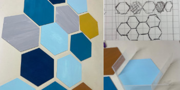 Hence, my idea
is to build the wall using hexagon forms, like simulating a bee panal. That kind of structure could
cover all or part of the wall. Could be built by modules, and each one could have different colors,
like legos that are sticked together. Thus, some hexagons could be blank and other could containg
funkos. In this way, not every hexagon serve as shelve, and coulb be build using playwood, and
replace some the hexagons with 3D printed colored pieces. Like some art wall that I found on a
friend house, that you can observe in the image. But instead of being 2D Hexagons stick in the wall,
I can produce 3D hexagons inserted in a playwood wall.
Hence, my idea
is to build the wall using hexagon forms, like simulating a bee panal. That kind of structure could
cover all or part of the wall. Could be built by modules, and each one could have different colors,
like legos that are sticked together. Thus, some hexagons could be blank and other could containg
funkos. In this way, not every hexagon serve as shelve, and coulb be build using playwood, and
replace some the hexagons with 3D printed colored pieces. Like some art wall that I found on a
friend house, that you can observe in the image. But instead of being 2D Hexagons stick in the wall,
I can produce 3D hexagons inserted in a playwood wall.
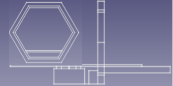
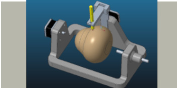
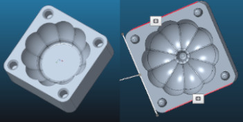
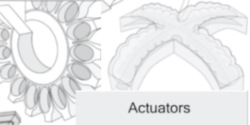
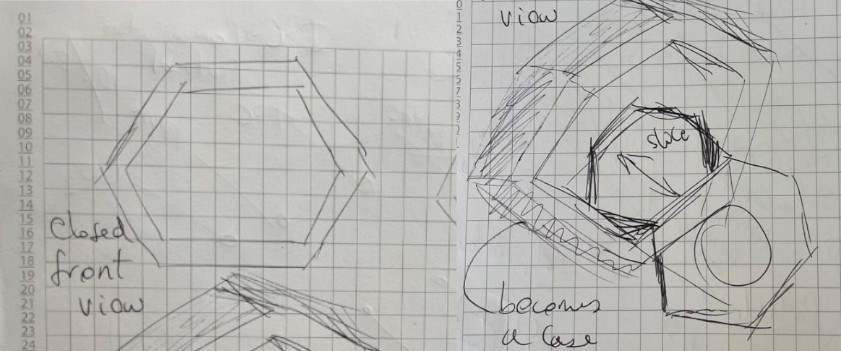
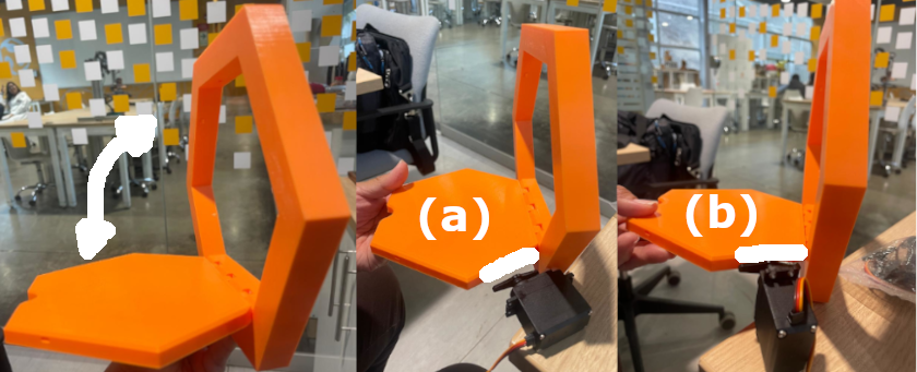
The following image tried to provide a description of the functioning process of each 3D printed hexagon. The shelve could be closed and then could be actioned, the hexagon top is opened and a hexagon or rectangular platform could slides to showcase a funko
 I
visited some 3D printing designs repositories like thingiverse looking for hexagon shelves models,
and
found two that I think could be useful. The first are big hexagon sehlves,
functioning
in a modular way, the couple forming some kind of big shelve that could be ensamble. The problems
with
the design is that it seems very slim and it would need some kind of frame to contain a top. So the
frame could also provide support to have a mobile top. Considering that I want to open and close
them. I
decide to look for hexagon wall shelves, that sometime I have seen used to hold flowerpots. Finally,
I
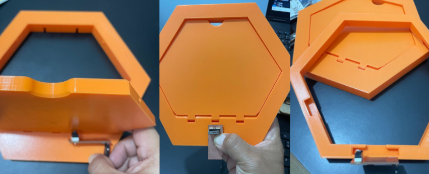
found a Wall mounted foldable modular hexagon shelf (print in place) desing by RiverRaid. You can observe
that the design include one printed piece, that is foldable and have a frame, that allows to open
and
close the top, and support small flowerpots.
I
visited some 3D printing designs repositories like thingiverse looking for hexagon shelves models,
and
found two that I think could be useful. The first are big hexagon sehlves,
functioning
in a modular way, the couple forming some kind of big shelve that could be ensamble. The problems
with
the design is that it seems very slim and it would need some kind of frame to contain a top. So the
frame could also provide support to have a mobile top. Considering that I want to open and close
them. I
decide to look for hexagon wall shelves, that sometime I have seen used to hold flowerpots. Finally,
I
found a Wall mounted foldable modular hexagon shelf (print in place) desing by RiverRaid. You can observe
that the design include one printed piece, that is foldable and have a frame, that allows to open
and
close the top, and support small flowerpots.

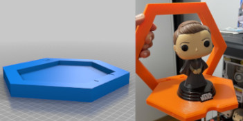
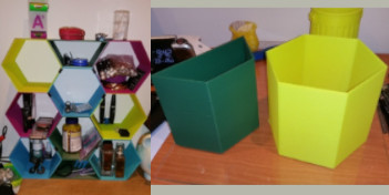
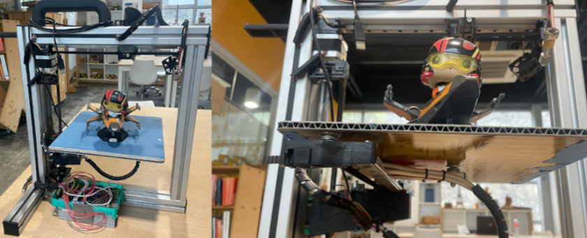
I donwload the files to printed them, and to have an idea about dimensions. Because I need to test the diferent funko models, not every model present same characteristics. So I can decide if I could used packed or unpacked funkos. I have some problems when printing. i think that ir was because my filament was expose to much time to humity.
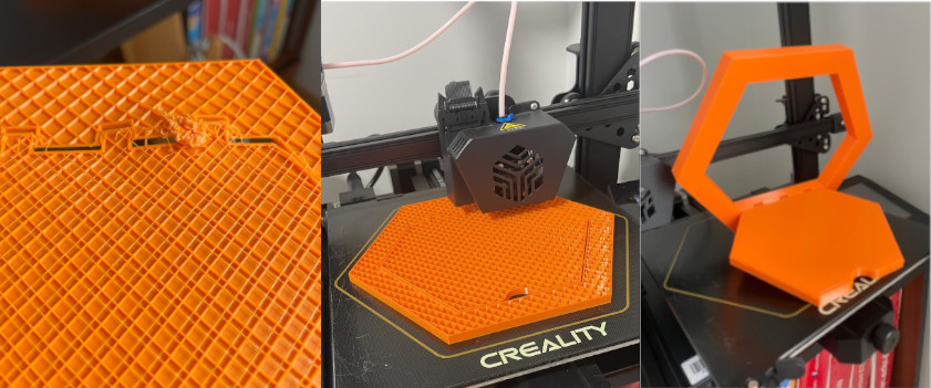
I test product dimensions using different kind of funkos, because some special design are wider or taller. So I can decide for which kind of funkos I will develop my final design. I also notice that build something for the unpacked funkos will need something bigger

Looking for mechanisms that I can use
Thinking that I would need to use stepper motors and servo motors that I could use. I comented my idea during a global open time, thus I found some interest ideas, from artist and from previos FabAcademy Students. First I found Gonzalo Siu final project. .

During global open time I comment about my final prject idea and they suggest me to watch a group project develop by Benjamin Bente and Joany Jonathan from waag fab lab called the motion wall final project. .
With my instructor support, we review the components that I'm gonna need for my final project in
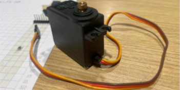
order to decide which output could be the starting point. So I decide to start with a Servo motor
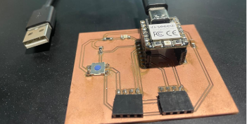
that I'll probably use to open the hidden shelve. The following picture show the potential devices
that I would use for my final project. I would use 2 Servo Motors, so the option could be to
fabricate one or two boards. I decide to fabricate one. 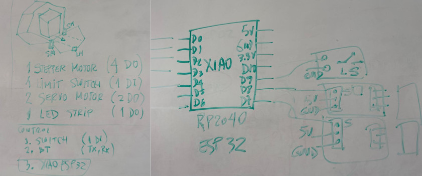
On week 9, with my instructor support, we review the components that I'm gonna need for my final project in order to decide which output could be the starting point. So I decide to start with a Servo motor that I'll probably use to open the hidden shelve. The following picture show the potential devices that I would use for my final project. I would use 2 Servo Motors, so the option could be to fabricate one or two boards. I decide to fabricate one.
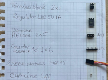 By
acknowledging that servo motors function with 5V and common power supply sources provide 12V, we
select the following components for this main board. It consists of the following:
By
acknowledging that servo motors function with 5V and common power supply sources provide 12V, we
select the following components for this main board. It consists of the following:
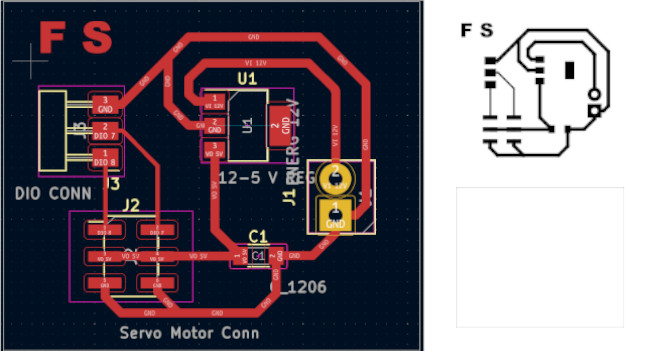
This is the pcb design where you can see all the components. You can download design file and
the SVG files here.
I proceeded with machining and soldering the PCB board
 For functional
testing I used a modified coding provided by Adrian-Torres
For functional
testing I used a modified coding provided by Adrian-Torres
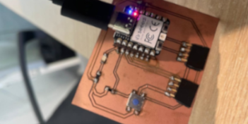
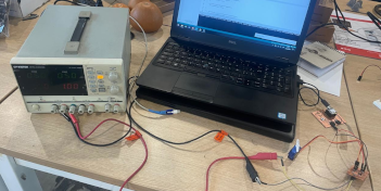
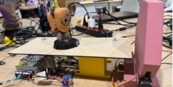
The following photo shows all system connection to test. I used XIAO RP2040 from Week 8 to test the
board and the output device (Servomotor) 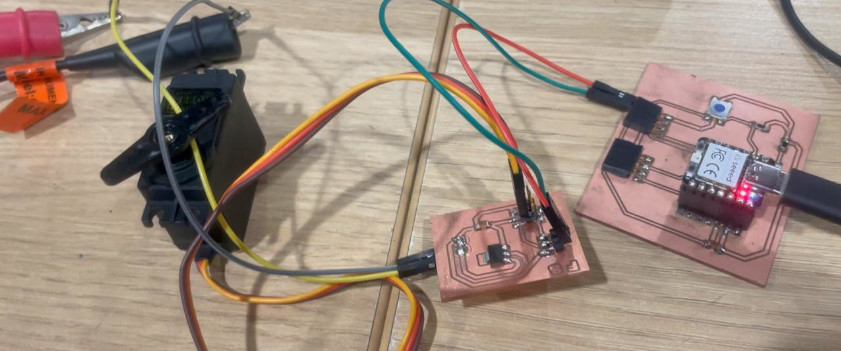
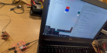
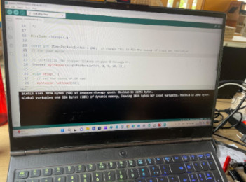
The final test was made runing the conding Arduino IDE and using a variable energy source, like shown in the following video
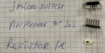
On week 12, with my instructor support, we review the components that I'm gonna need for my final project in order to select input device. The only input is a limit switch, that is going to activate all the complete system to stop the stepper motor that will show the funko. The following picture show the potential devices that I would use for my final project.
 By
acknowledging that switch function we select the following components for this main board:
By
acknowledging that switch function we select the following components for this main board:
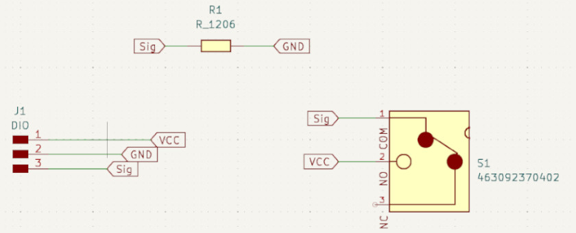
This is the schematic where you can see all the components. You can download Schematic design file
and the PNG file here.
This is the pcb design where you can see all the components. You can download design file and
the SVG files here.

The final PCB image is shown below
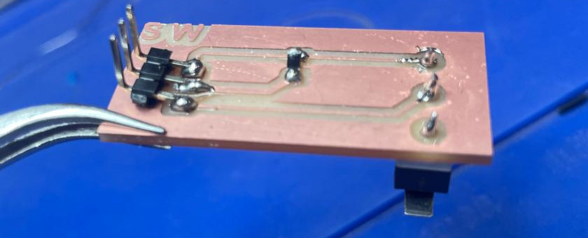
The following photo shows all system connection to test. I used XIAO RP2040 from Week 8 to test the
board and the output device (Servomotor) 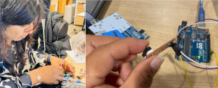
On 14th week, with my instructor support, we review the components that I'm gonna need for my final project in order to decide which could require a wifi or bluethooth communication. So I decide to start with a Servo motor that I'll intent to use for opening the hidden shelve. The following picture show the potential devices that I would use for my final project. I would use 2 Servo Motors, so I decide to execute a bluethooth connection, using an app to activate the servomotor.
I used
the board design and fabricated at
week 9 ,the following are its components:
This is the pcb design where you can see all the components. You can download design file and
the SVG files here.
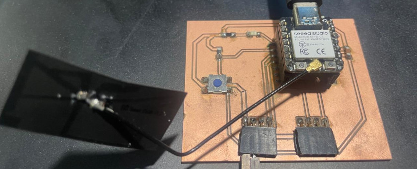
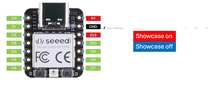
I used the board design and fabricated at week 8 , because its design includes a push bottom and a LED, and have DIO pins to connect the servo motor controller, and replaced the XIAO RP"=$= by XIAO ESP32C3. The following are its components:
This is the pcb fabricated where you can see all the components. You can download design file and
the SVG files here.
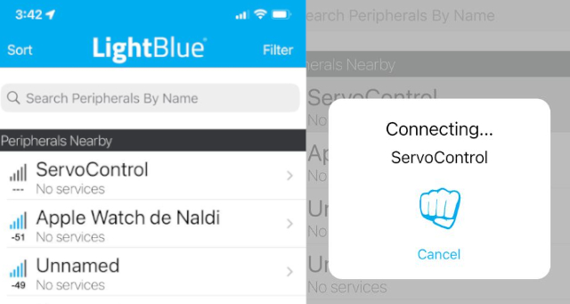
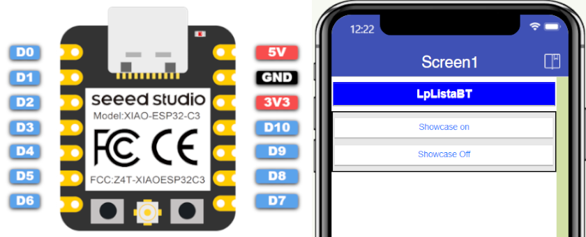
First I decide to test the microcontroller following the steps suggested by Seeedstudio here. and use the LightBlue App to control my servomotor
In the following images you can observe the process

You can download the KiDCad library here.
In the follorwing video you can observe the final result when controlling the ServoMotor
On week 15, we first generated a code for a 180 arm movement. The code will need to recognize the serial imput that will come from the computer interface to control a microservo SG90
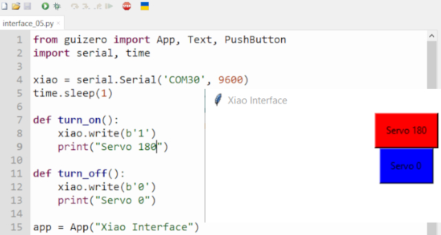
You can download the Arduino Ide and Thonny Programing files here.
In the follorwing video you can observe the final result when controlling the ServoMotor
I have two options to develop my final project's main board, that does not change its general structure, but its interface to activate it.
 Its advantage it is not only wireless control, but anyone that could use also LightBlue and introduce a string-value
to activate it.
Its advantage it is not only wireless control, but anyone that could use also LightBlue and introduce a string-value
to activate it.
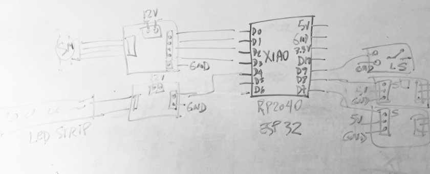
After reviewing the mechanical and electronics requierements for my final project, its schema is shown in the following
image.

Thus, I would proceed to analyse system integration within mechanical design that would be develop for the project:


Wellcome to the process of trying to make almost something